Blade Forces
|
A tidal turbine blade is subjected to forces in a similar way to that of a wind turbine blade; force is caused by the external flow travelling over the solid body causing a pressure difference. Forces can be split up into two; drag force (FD) and lift force (FL). Drag force is force exerted by a flowing fluid on a body in the flow direction [7]. Lift force is one which acts normal to the flow direction [7]. The image to the right represents the two force components for a streamlined body as well as resultant force(FR).
|

Picture courtesy of Neles and Jamsbury,2012 [8]
|

Picture courtesy of Neles and Jamsbury,2012 [8]
|
Drag force can be split up into two parts. One component of the drag force is due to wall shear stress, known as the skin friction drag, which is a function of the surface roughness of the turbine blade. The other component is the pressure drag, which is equivalent to the frontal area, and the pressure difference between the leading edge and the trailing edge of the body [7]. This can be increased if fluid flow separates from the body, therefore producing a low pressure region behind the body [8] . This area, where effects of the body on velocity are felt, is called the wake. The image below highlights this area of separation which leads to an increase in pressure drag.
|
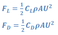
Lift and Drag Equations
|
Where ρ is density of the fluid (Kg/m3) A is frontal area (m2). U is flow velocity (m/s) CL is lift coefficient (dimensionless) CD is drag coefficient (dimensionless). |
Bending Stress
Bending stress is an important consideration for consideration of turbine blade loads. This is ‘normal stress that is induced at a point in a body to loads that cause it to bend [9]. Through Flexural theory, it is believed materials used in tidal turbines will exhibit linear-plastic behaviour, by deflecting in accordance with Hooke’s law [9].
Vertical Shear
Due to the rough seabed, a non-uniform profile rises, imparting a shear force on the flow [5]. Therefore, during one revolution, blades will experience variation in the mean onset flow velocity and therefore the magnitude of the turbulent fluctuations [5]. Through an approximation, a power law is commonly used to describe the vertical shear profile, expressed as:

The shear profile can have an effect on the horizontal velocity observed by the blade [5]. It is also noted that the effect of rotational sampling can be observed, where the velocity fluctuation on the rotating blade is greater that at the hub. This is due to rotor slicing through multiple eddies, contributing to the unsteady loads experienced [5].
Blade Root Forces
The blade root is the heaviest and thickest part of the blade since it carries the blade structure and it is the connection point between the blade and the hub [10]. The root is required to resist high moments (both in-plane and out-of-plane) and torques which are transmitted by aerodynamic forces through the blade, and therefore stress and strains on the blade root [10]. This high stress is in part due to the dramatic change in cross-sectional area from the blade to the blade root [10].
Extreme and Fatigue Loading
Finally it is important to appreciate the significance difference between fatigue and extreme loading. Extreme loading describes the loads which would occur as a result of extreme flow velocity. These loading events are typically associated with large scale turbulent eddies, causing high drag force, and therefore high stress [6]. Extreme loading appears to be most significantly affected by mean flow speed, longitudinal turbulence intensity, wave action, and height of the hub with which the rotor is attached [6].
Fatigue loading is different from extreme loading in that it also takes into account the fatigue properties of the material [11]. The materials most widely used in turbine blade construction are composites [5]. Despite having advantages over other materials such as the ability to tailor for specific mechanical properties [12], composites are complex to analyse for fatigue loading due to the different materials involved.
For calculating the fatigue loading on a tidal turbine, it is standard practice to calculate Damage Equivalent Loads (DELs) [6]. DELs are computed using the Rainflow cycle counted load data, caused by a single stress range repeating at a single frequency [9]. DELs are characterised using the equation below [6][13]:

|
Where LN is equivalent stress for N cycles
N is number of cycle repetitions in turbine lifetime ni is number of rain flow cycles at stress range m is the negative inverse of the slope on the material’s Wöhler curve |
