Design
Design Requirements
For consideration of the apparatus required, it was important to identify what would be needed to carry out the aims and objectives successfully. The following aspects were required to be considered when creating the final design:
- Create an aerofoil profile suitable for analysis and which would be suitable for the size of flume to represent the tidal turbine blade. For appropriate attachment, a spar was included in the design of the blade
- Spar to be made out of bar which would be stiff enough to allow bending under stress
- Develop a test rig which can support the test piece
- For the possibility to look at the effect with increasing angle of attack, the ability to rotate the blade relative to direction of flow
- Instruments which would allow for the flow speed and the force being subjected onto the blade to be measured
- Ability to determine a timestamp in order to be able to correctly relate the forces with the associated flow speed and turbulence intensity.
Test Rig DesignThe test rig is required to support the test piece in the 20m recirculating flume. The test rig was also required to be rigid enough so that all the force caused by the flow was felt by the spar and load cell only. By using a 12mm thick aluminium plate, this prevents the plate from succumbing to any overturning moment. The plate was made out of aluminium in order to prevent corrosion
|
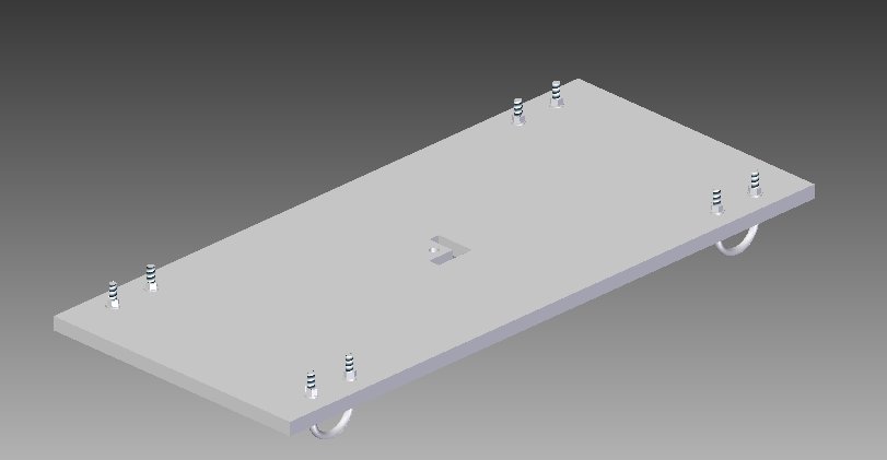
Picture Courtesy of SolidEdge
|
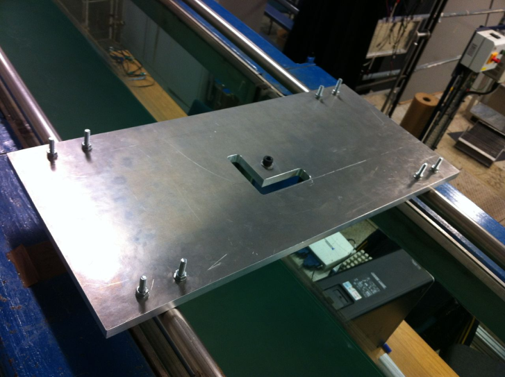
Picture Courtesy of Author
|
|
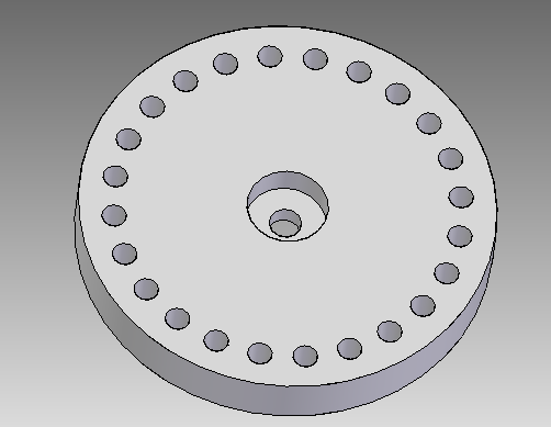
Flange Design
The flange was designed to allow to change the angle of attack with which the spar/blade has with the flow. The flange created had holes cut which are incremented 15 degrees from each other. With the use of two flanges, having one fixed to the load cell and allowing the other to rotate, the requirement could be achieved. In order to prevent the spar from freely rotating, a recess was cut into the flange. This can be seen in the image below left, whilst the image to the right shows the same flange created using SolidEdge.

Picture Courtesy of Author
|
Picture Courtesy of Author using SolidEdge
|
Spar and Strain gauge selection
In order to select apparatus which would allow for suitable bending under stress, Hooke's law was used to calculate the strain of the spar with known cross-sectional area dimensions. The length of the spar was selected to be 0.6m due to the constraints of the test flume. Using the equation for Hooke's law, the rating of the strain gauges required was selected to be 350 ohm
Blade Design
The design of the blade was chosen to resemble a simple symmetrical NACA aerofoil. This selection will allow for simple calculations during the analysis stage of the project. A NACA0030 aeorfoil shape was selected so that the blade was thick enough to withstand the forces of the flume while accomodating the spar.
Due to a lack of remaining workshop time, the aerofoil design was not completed. The image below shows the design of the aeorfoil created on SolidEdge
Due to a lack of remaining workshop time, the aerofoil design was not completed. The image below shows the design of the aeorfoil created on SolidEdge

Picture Courtesy of Author Using SolidEdge
Force Measurement
For measurement of blade root forces, a load cell was selected. due to it having high sensitivity to load. As mentioned, strain gauges were used to measure the force exerted by the fluid flow. This was carried out using a full Wheatstone Bridge Circuit.

Wheatstone Bridge Circuit. Picture Courtesy of National Instruments [24]
